In my last post, I had mentioned about the issue of fuse getting blown off. The cause of the problem was traced to PA stage and I did a workaround to skip the problem and continue with the receiving part. As a workaround,I had removed the RF Choke through which power was being supplied to the final PA stage, so that the PA stage was isolated.
Now that the receiving is working well, I started thinking on the first issue i.e blowing fuse issue. This time there were lot of suspects in my list :). The output transformers, the SWR transformers, driver transistors and many others.
The problem is, when ever I provide dc supply voltage to the PA stage, the transceiver draws a hell lot of current and the supply voltage reduces to as low as .68V from 12V. And the transceiver won't power on. And if the power connector is removed, it blows off the fuse as well.
There can be many possibilities for this issue like wrong connection in output transformer, shorts in any of the transformers wound on Binocular cores, High bias voltage reaching the MOSFET gate which in turn could conduct all the current from Drain to Source, any damaged smd components in the PA stage and many others.
The first thing to be done was checking for shorts in output transformers after removing from the PCB. But couldn't find anything wrong in the transformers. Next I checked the bias voltages to the MOSFET gates which came from the LM2931 IC. That too looked OK.
What now?? There could be some RF voltage coming into MOSFET gate which is driving this MOSFET crazy. The RF voltages will go undetected in DMM(Digital Multi Meter). So I connected an RF Probe and checked for the existence of any RF voltages in the MOSFET Gate. RF voltage in Gate=0V. So these experiments continued. I never suspected the PA MOSFETs , because they were bought from ebay.com from US and brought to India by one of Vimal's(VU3CPE) friend. (Vimal a friend of mine and myself are sourcing the components together and building the mcHFs individually)
Also Vimal had tried replacing his MOSFETs with one which was bought sometime later(We had bought the MOSFETs twice, because of the first package getting lost during transit and later on getting back the same. It's a long story:). Anyways we ended up having two sets of same MOSFETs, Toroids etc.)
So all these things made us believe that MOSFET is not the culprit.
Experimented many things, but all resulted in high current drawing and shorting the supply voltage. With all the possibilities exhausted, I turned to MOSFET. The MOSFET used are two numbers of RD16HHF1 made by Mitsubishi. I took out the MOSFET from the circuit and tried to check the Vgs vs Id(Gate voltage vs Drain current).
Lets go through some basics of operation of a MOSFET.
MOSFETs are nothing but valves,in which the current flow can be controlled by varying the Gate voltage. So till the Gate voltage reaches a certain value, the MOSFET will remain non-conducting. This value is know as the Threshold voltage or Vgs(th) or simply Vth. Usually this would be somewhere around 3-4 Volts. That means till you supply at least 4 Volts to the Gate, the MOSFET will remain off. This region of operation is called "Cut-Off" region. Once you increase gate voltage above 4 Volts, only then the MOSFET will start conducting.
Back to our MOSFET experiment. I needed to check how our MOSFET was behaving in the cut-off region, i.e. when Vgs<4v. I had to set the Vgs to '0'. So shorted the MOSFET Gate to the Source and connected it to a negative of my power supply with voltage set to 10V. The power supply is a small one capable of sourcing only about 1.2A. The DMM was kept connected to the power supply. As soon as I connected the positive lead of the power supply to the Drain, the supply voltage dropped to 0.68V almost shorting the power supply. Repeated the experiment, this time with the DMM connected as an ammeter in series to check the current draw. The whole of the current which the power supply could source was flowing through the MOSFET. I couldn't believe this :) there seems to be no effect of the Gate Voltage(Vgs) on the Drain current(Id). And this confirmed that the MOSFET was the one shorting the entire circuit.
Meanwhile, Vimal(VU3CPE) got his MOSFETs replaced by sending his completed SDR Tranceiver to VU3GEK and it is transmitting fine now. The video of the same is available in YouTube. Also Vimal is getting a few number of RD16HHF1 for both of us from VU3GEK, so I m waiting for the new MOSFETs to arrive. I am experimenting with IRF510s till I get the RD16HHF1s. The Drain, Source pins are reversed for IRF510. I have used IRF510s in past for the BITX transceivers that I had built. The IRF510 being a switching MOSFET, will nowhere match the performance of RF MOSFET RD16HHF1, but still, something is better than nothing...at least for the time being. :)
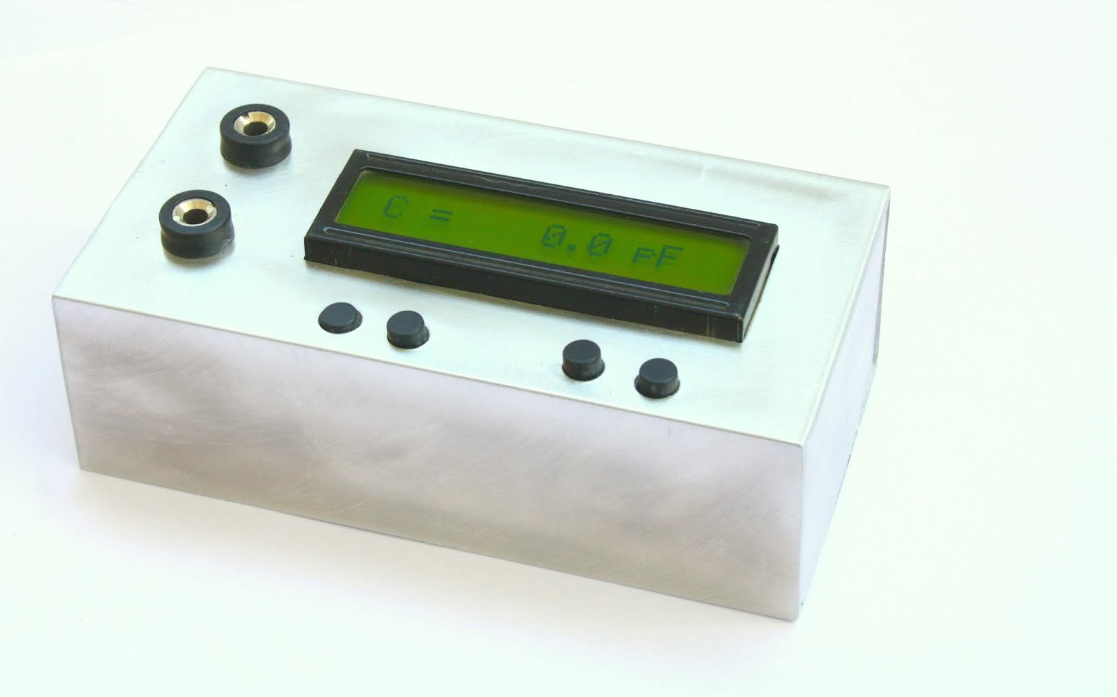
 This one is a small useful measuring device which would help you in homebrew projects. Usually it is difficult to find a commercial meter which can measure the range of Inductance and Capacitance that we HAMs need. If you are involved in some RF ameteur radio circuit homebrewing, then this tool would be of a great help as it has been for me.
I had been using this circuit constructed on a general pcb (vero board) and using it for past few years. And this had been helpful to me in most of my homebrew projects including BITX20,BITX40,MCHF and many more.
So I thought of printing a commercial quality PCB from some fab house here. The PCBs are ready now and below are the photos.
This one is a small useful measuring device which would help you in homebrew projects. Usually it is difficult to find a commercial meter which can measure the range of Inductance and Capacitance that we HAMs need. If you are involved in some RF ameteur radio circuit homebrewing, then this tool would be of a great help as it has been for me.
I had been using this circuit constructed on a general pcb (vero board) and using it for past few years. And this had been helpful to me in most of my homebrew projects including BITX20,BITX40,MCHF and many more.
So I thought of printing a commercial quality PCB from some fab house here. The PCBs are ready now and below are the photos.